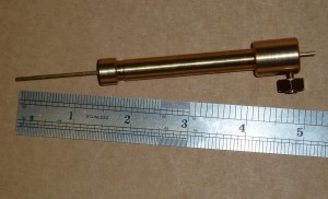
 Having recently faced some cylinder drilling, I finally got around to making a depth gauge. It took about a morning. The sizing is very-much determined by available parts, starting from the springs and having some 3/8″ OD brass tube with nice thick walls (ID approx 1/4″) to hand. Two springs gave me about the 1 1/2″ of gauge travel I wanted.
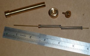
No dimensioned drawings this time, but see below for a photograph of the disassembled gauge from which you should be able to work it out. In lieu of drawings, here are a few notes…
- The end cap was made first, drilled to about 1/64″ less than the OD of the brass tube. You can see where I then turned down the tube to get a nice press fit. I’m very fond of press fits: most satisfying and clean. If you over-do it then you can always braze/solder but it never looks so nice. I have a small arbor press.
- The other end of the tube was threaded using ME 3/8″ x 32 TPI since this matches the tube OD and is a fairly fine thread.

- The 1/4″ spring-stopper on the 1/16″ central “spike” was another press fit thanks to some metal forming as I parted it off. Don’t bend the spike!
- The thumb screw was made by tapping (5BA) a shaped and parted-off piece of hex stock, screwing a 5BA cheese-head screw firmly into place with a bit of thread-lock and then turning away most of the head. NB: face, chamfer, drill, tap, insert screw and turn-off head are all done without removing the work from the chuck.
The images above are links to larger photographs.