The benefits of the Atmel Studio 6 IDE (if you can get to grips with it) are described in various places so I won’t repeat them here. For my part, I began using it with an AVR Dragon board for programming micrcontrollers directly (i.e. not using the arduino or similar development boards). I have also started writing some libraries and found the Arduino IDE to be a bit limited. I wanted to be able to use Atmel Studio to create programs that would also be usable, ideally with no change, on Arduino boards with the Arduino IDE being used. A further complication is that I have both Uno and Leonardo boards, which have a different processor and so need separate code compilation.
There are several guides to achieving this kind of thing (Google “atmel studio arduino”) but most seemed to be rather involved and not well suited to having boards with different processors. The best I found, which is not at all “involved”, was by Elco Jacobs. He approached the task with the kind of strategy I wanted and his account and example code saved me a lot of trial and error. There were a few points where I wanted to do things a little differently; this post is about the changes and some experiences along the way. It is partly written so I remember how it works…
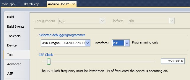
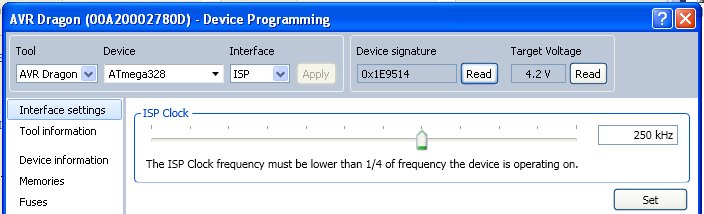
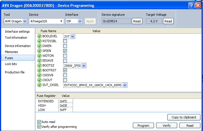
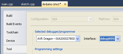
There are two main parts to getting things to work: compiling the code and uploading to the arduino. Although I do have an AVR Dragon and could have used in-system programming (ICSP), I wanted to be be able to use the normal process of using the serial upload over USB and to leave the bootloader intact.
The end point of the following, which is not as complicated as it looks, is that a new Arduino IDE compatible “sketch” can be begun by clicking the New Project icon in the tool bar and selecting one of two templates according to the target board.
1 – compiling the code
This is the easier part of the two. The approach taken can be broken down into two: configuring Atmel Studio and creating a C++ harness within which a verbatim Arduino sketch can be executed. Since there are differences between Uno and Leonardo, I created two versions of the following steps: one for each board.
1a) configuring Atmel Studio
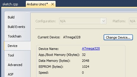
Start off creating a new Executable C++ project and choose the correct microcontroller type (ATmega328P for Uno and ATmega32U4 for Leonardo).
Open the project properties and select the “toolchain” set of properties. Under “AVR/GNU C++ Compiler” you should see several groups of properties.
Directories
Add two entries to locate the source files for the Arduino core and be sure to un-check the “relative path” option. These are to be found wherever you installed the Arduino IDE. For me, and for the Uno, they are:
- C:\Program Files\Arduino\hardware\arduino\cores\arduino
- C:\Program Files\Arduino\hardware\arduino\variants\standard
The second of these would have “leonardo” instead of “standard” for the Leonardo board.
If you use any of the Arduno libraries, you must add additional entries to “Directories” for each one: e.g. “C:\Program Files\Arduino\libraries\EEPROM”
Optimisation
Set the compiler to optimise for size and check the -ffunction-sections option.
In addition, under “AVR/GNU Linker”, set the optimisation to garbage collect unused sections.
Symbols
Add two entries (these are applicable for Uno and Leonardo; the first denotes “Arduno 1.0 libraries” and the second denotes a 16MHz clock):
- ARDUINO=100
- F_CPU=16000000L
1b) the sketch harness
Two C++ files are used. One will contain the sketch and one contains a few lines of code to hook in the Arduino core libraries and the main program from which the usual “setup()” and “loop()” components of a sketch are called. I named these “sketch.cpp” and “main.cpp” respectively.
This arrangement means that if you want to compile the same sketch with different Arduino boards as the target you can use exactly the same sketch.cpp in two different Atmel Studio projects. The neatest approach would be to point both projects at the same file, rather than copying it, of course!
sketch.cpp
If you already have an arduino sketch (.ino or .pde) then the content of it may just be copied and renamed sketch.cpp.
There are, however, two small extras that may be required at the top of the sketch:
- if there are any functions other than void setup() and void loop() then it is necessary to add a function prototype. This means that if there is a function “void serialMessage()” then you must add “void serialMessage();” at the head of sketch.cpp in addition to the function itself. Google “arduino function prototype” to find out more.
- if a library such as EEPROM is used then it may be necessary to change the #include to point to the .cpp file rather than the .h file. If EEPROM.h does NOT contain a #include <EEPROM.cpp> then you need to point to EEPROM.cpp from the sketch otherwise the compiler will not find the definition of EEPROM. Wire and SD libraries are even more tedious in that there are 1 or more additional files to include… check the error messages, add the #include and if necessary also add a new directory in the C++ Compiler options.
Keep these “extras” together and above the body of the sketch with an appropriate comment line if you intend to share the code (or just want to be neat, keep sane…).
As an alternative to adding prototypes manually, it is possible to compile and upload in the Arduino IDE and then to grab the C++ code that the IDE creates during its compile process. To find where this is, go to File|Preferences and set the Arduino IDE to “Show verbose output during: [x] compilation”. This will cause the temporary directory containing the C++, all compiled intermediates and the “.hex” file used by the uploader to be revealed. The .cpp should be the same as the sketch but with a few extra lines near the top of the listing. Replace the template sketch.cpp with this.
main.cpp
This is really just a combination of two of Elco Jacobs’ files with a few edits. Since things are a little different for Uno and Leonardo, the main.cpp file differs between the two versions. Remember that the end point is a separate template for each board so two versions are created rather than having to comment out or uncomment code blocks according to the board in use.
NB: You may have to uncomment or add one or mode .cpp or .h files from the Arduino core libraries. See the "//Unused source files" but also be aware there may be some not listed in that section.
main.cpp for Uno1
2
3
4
5
6
7
8
9
10
11
12
13
14
15
16
17
18
19
20
21
22
23
24
25
26
27
28
29
30
31
32
33
34
35
36
37
38
39
40
41
42
43
44
45
46
47
48
49
50
51
52
53
54
55
| #define ARDUINO_MAIN
// Disable some warnings for the Arduino files
#pragma GCC diagnostic push
#pragma GCC diagnostic ignored "-Wsign-compare"
#pragma GCC diagnostic ignored "-Wattributes"
#pragma GCC diagnostic ignored "-Wunused-variable"
#pragma GCC diagnostic ignored "-Wuninitialized"
#include <Arduino.h>
extern "C"{
#include <pins_arduino.h>
}
/*
* Libraries
*/
// Standard Arduino source files for serial:
#include <HardwareSerial.cpp>
// Other source files, depends on your program which you need
#include <Print.cpp>
#include <New.cpp>
#include <wiring.c>
#include <wiring_digital.c>
#include <wiring_analog.c> //analog read/write functions
#include <WString.cpp>
#include <WMath.cpp>
#include <Stream.cpp>
// Unused source files:
//#include <WInterrupts.c>
//#include <wiring_pulse.c>
//#include <wiring_shift.c>
//#include <IPAddress.cpp>
//#include <Tone.cpp>
// Restore original warnings configuration
#pragma GCC diagnostic pop
/*
* Main code called on reset; the sketch harness
*/
int main(void)
{
init();
setup();
for (;;) {
loop();
if (serialEventRun) serialEventRun();
}
return 0;
} |
#define ARDUINO_MAIN

// Disable some warnings for the Arduino files
#pragma GCC diagnostic push
#pragma GCC diagnostic ignored "-Wsign-compare"
#pragma GCC diagnostic ignored "-Wattributes"
#pragma GCC diagnostic ignored "-Wunused-variable"
#pragma GCC diagnostic ignored "-Wuninitialized"

#include <Arduino.h>
extern "C"{
	#include <pins_arduino.h>
}

/*
* Libraries
*/
// Standard Arduino source files for serial:
#include <HardwareSerial.cpp>

// Other source files, depends on your program which you need
#include <Print.cpp>
#include <New.cpp>
#include <wiring.c>
#include <wiring_digital.c>
#include <wiring_analog.c> //analog read/write functions
#include <WString.cpp>
#include <WMath.cpp>
#include <Stream.cpp>

// Unused source files:
//#include <WInterrupts.c>
//#include <wiring_pulse.c>
//#include <wiring_shift.c>
//#include <IPAddress.cpp>
//#include <Tone.cpp>

// Restore original warnings configuration
#pragma GCC diagnostic pop

/*
* Main code called on reset; the sketch harness
*/
int main(void)
{
	init();

	setup();

	for (;;) {
		loop();
		if (serialEventRun) serialEventRun();
	}
	return 0;
}
main.cpp for Leonardo1
2
3
4
5
6
7
8
9
10
11
12
13
14
15
16
17
18
19
20
21
22
23
24
25
26
27
28
29
30
31
32
33
34
35
36
37
38
39
40
41
42
43
44
45
46
47
48
49
50
51
52
53
54
55
56
57
58
59
60
61
62
63
| #define ARDUINO_MAIN
// Disable some warnings for the Arduino files
#pragma GCC diagnostic push
#pragma GCC diagnostic ignored "-Wsign-compare"
#pragma GCC diagnostic ignored "-Wattributes"
#pragma GCC diagnostic ignored "-Wunused-variable"
#pragma GCC diagnostic ignored "-Wuninitialized"
#include <Arduino.h>
extern "C"{
#include <pins_arduino.h>
}
/*
* Libraries
*/
// Arduino Leonardo source files for serial:
#define USB_VID 0x2341
#define USB_PID 0x8036
#include <CDC.cpp>
#include <USBCore.cpp>
#include <HID.cpp>
// Other source files, depends on your program which you need
#include <Print.cpp>
#include <New.cpp>
#include <wiring.c>
#include <wiring_digital.c>
#include <wiring_analog.c> //analog read/write functions
#include <WString.cpp>
#include <WMath.cpp>
#include <Stream.cpp>
// Unused source files:
//#include <WInterrupts.c>
//#include <wiring_pulse.c>
//#include <wiring_shift.c>
//#include <IPAddress.cpp>
//#include <Tone.cpp>
// Restore original warnings configuration
#pragma GCC diagnostic pop
/*
* Main harness for sketch.
*/
int main(void)
{
init();
#if defined(USBCON)
USBDevice.attach();
#endif
setup();
for (;;) {
loop();
if (serialEventRun) serialEventRun();
}
return 0;
} |
#define ARDUINO_MAIN

// Disable some warnings for the Arduino files
#pragma GCC diagnostic push
#pragma GCC diagnostic ignored "-Wsign-compare"
#pragma GCC diagnostic ignored "-Wattributes"
#pragma GCC diagnostic ignored "-Wunused-variable"
#pragma GCC diagnostic ignored "-Wuninitialized"

#include <Arduino.h>
extern "C"{
	#include <pins_arduino.h>
}

/*
* Libraries
*/
// Arduino Leonardo source files for serial:
#define USB_VID 0x2341
#define USB_PID 0x8036
#include <CDC.cpp>
#include <USBCore.cpp>
#include <HID.cpp>

// Other source files, depends on your program which you need
#include <Print.cpp>
#include <New.cpp>
#include <wiring.c>
#include <wiring_digital.c>
#include <wiring_analog.c> //analog read/write functions
#include <WString.cpp>
#include <WMath.cpp>
#include <Stream.cpp>

// Unused source files:
//#include <WInterrupts.c>
//#include <wiring_pulse.c>
//#include <wiring_shift.c>
//#include <IPAddress.cpp>
//#include <Tone.cpp>

// Restore original warnings configuration
#pragma GCC diagnostic pop

/*
* Main harness for sketch.
*/
int main(void)
{
	init();

	#if defined(USBCON)
	USBDevice.attach();
	#endif

	setup();

	for (;;) {
		loop();
		if (serialEventRun) serialEventRun();
	}
	return 0;
}
Try it!
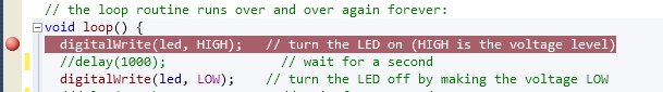
Given the above, it should be possible to cut and paste the “blink” sketch into sketch.cpp and compile using F7 or the Build menu.
2 – uploading
Uploading can be a bit of a pig. The smooth way the Arduino IDE works is, for me, its main redeeming feature. There are several options and I began by using the rather nice MegunoLink tool (which may be downloaded for free and a donation made). MegunoLink allows you to locate the .hex file that is created after compilation and to upload it with ease. It uses avrdude behind the scenes, just as the Arduino IDE does. MegunoLink also includes a rather nice plotting feature, where you can send formatted data over Serial and plot it in real time. Nice! The MegunoLink site also gives an alternative recipe for using AtmelStudio alongside MegunoLink.
For better integration of avrdude with Atmel Studio, you have to do a bit of fiddling. A lot more fiddling was required to get a usable approach for the Leonardo. The end point is upload over the normal USB connection by the click of a mouse or keyboard shortcut inside Atmel Studio.
Setting up for Uno
Tools > External Tools…
Add a new tool, give it a title like “Uno Serial Upload” and set it up something like this (you may need to change the file paths to match where you installed the Arduino IDE to and you may need to change “COM3”):
- Command = C:\Program Files\Arduino\hardware\tools\avr\bin\avrdude.exe
- Arguments = -C"C:\Program Files\Arduino\hardware\tools\avr\etc\avrdude.conf" -patmega328p -carduino -P\\.\COM3 -b115200 -Uflash:w:"$(ProjectDir)Debug\$(ItemFileName).hex":i
- I also checked the “Use Output window” option, which causes the avrdude messages to appear where compiler messages usually do.
A new external tool should be accessible from the Tools menu on saving this data. In use it is essential to first select (click on) the project in the Project Explorer window. This is so that the $(ItemFilenName) is correct. If you have sketch.cpp selected then Atmel Studio tries to invoke avrdude to upload sketch.hex, which does not exist.
Setting up for Leonardo
It would have been nice if the same recipe as for the Uno could be followed, with a simple change to the -p and -c flags in the arguments list. Sadly, the Leonardo needs to be given a kick before it is ready to receive avrdude. This is pretty ugly design IMO. The “kick” is given by making a connection at 1200 Baud, waiting a while for the Leonardo to run its bootloader and get ready and only then trying to use avrdude. The COM port usually changes after the kick and changes back when avrdude finishes. Usually! Yes, “usually”: sometimes I found it didn’t change back after running avrdude if there was an error condition. You can watch this happening in the Device Manager or upload a sketch in the Arduino IDE with verbose output enabled (go to Preferences to enable verbose output) to see the alternative COM port.
The easiest option was to adapt Elco Jacobs’ Python code, which is what the following code shows. Alternatively, you could just follow Elco’s approach but NB that I had problems due to space characters in the path to my Arduino IDE directory (i.e. “Program Files”).
Serial Uploader.py1
2
3
4
5
6
7
8
9
10
11
12
13
14
15
16
17
18
19
20
21
22
23
24
25
26
27
28
29
30
31
32
33
34
35
36
37
38
39
40
41
42
43
44
45
46
47
48
49
50
51
52
53
54
55
56
57
58
59
60
61
62
63
64
65
| import sys
import subprocess as sub
from time import sleep
# command line arguments are:
# first is the arduino IDE installation dir
# second is the arduino board type
# third is the .hex file
# fourth is the upload port
# fifth *** only used if Leonardo; omit otherwise *** serial port used to put leonardo into bootloader mode
arduinoPath = sys.argv[1]
boardType = sys.argv[2]
hexFile = sys.argv[3]
port2 = sys.argv[4]
if(boardType == 'leonardo'):
import serial
port = sys.argv[len(sys.argv)-1]
avrconf = arduinoPath + '/hardware/tools/avr/etc/avrdude.conf'
avrdude = arduinoPath + '/hardware/tools/avr/bin/avrdude'
avrsize = arduinoPath + '/hardware/tools/avr/bin/avr-size'
boardsFile = open(arduinoPath + '/hardware/arduino/boards.txt',
'rb').readlines()
boardSettings = {}
for line in boardsFile:
if(line.startswith(boardType)):
# strip board name, period and \n
setting = line.replace(boardType + '.', '', 1).strip()
[key, sign, val] = setting.rpartition('=')
boardSettings[key] = val
# check program size against maximum size
p = sub.Popen([avrsize,hexFile], stdout=sub.PIPE, stderr=sub.PIPE)#, shell=True)
output, errors = p.communicate()
if errors != "":
print 'avr-size error: ' + errors + '\n'
exit
print ('Progam size: ' + output.split()[7] +
' bytes out of max ' + boardSettings['upload.maximum_size'] + '\n')
programCommand = [avrdude,
'-C'+avrconf,
'-F' ,
'-p'+boardSettings['build.mcu'] ,
'-c'+ boardSettings['upload.protocol'] ,
'-b' + boardSettings['upload.speed'] ,
'-P'+port2,
'-Uflash:w:'+hexFile+':i']
# open and close serial port at 1200 baud. This resets the Arduino Leonardo
if(boardType == 'leonardo'):
ser = serial.Serial(port, 1200)
ser.close()
sleep(4) # give the bootloader time to start up
p = sub.Popen(programCommand, stdout=sub.PIPE, stderr=sub.PIPE)#, shell=True)
output, errors = p.communicate()
# avrdude only uses stderr, append it
print errors |
import sys
import subprocess as sub
from time import sleep

# command line arguments are:
# first is the arduino IDE installation dir
# second is the arduino board type
# third is the .hex file
# fourth is the upload port
# fifth *** only used if Leonardo; omit otherwise *** serial port used to put leonardo into bootloader mode

arduinoPath = sys.argv[1]
boardType = sys.argv[2]
hexFile = sys.argv[3]
port2 = sys.argv[4]

if(boardType == 'leonardo'):
   import serial
   port = sys.argv[len(sys.argv)-1]

avrconf = arduinoPath + '/hardware/tools/avr/etc/avrdude.conf'
avrdude = arduinoPath + '/hardware/tools/avr/bin/avrdude'
avrsize = arduinoPath + '/hardware/tools/avr/bin/avr-size'

boardsFile = open(arduinoPath + '/hardware/arduino/boards.txt',
   'rb').readlines()

boardSettings = {}

for line in boardsFile:
    if(line.startswith(boardType)):
          # strip board name, period and \n
        setting = line.replace(boardType + '.', '', 1).strip()
        [key, sign, val] = setting.rpartition('=')
        boardSettings[key] = val

    # check program size against maximum size
p = sub.Popen([avrsize,hexFile], stdout=sub.PIPE, stderr=sub.PIPE)#, shell=True)
output, errors = p.communicate()
if errors != "":
    print 'avr-size error: ' + errors + '\n'
    exit

    print ('Progam size: ' + output.split()[7] +
    ' bytes out of max ' + boardSettings['upload.maximum_size'] + '\n')

programCommand = [avrdude,
  	'-C'+avrconf,
   	'-F' ,
   	'-p'+boardSettings['build.mcu'] ,
   	'-c'+ boardSettings['upload.protocol'] ,
   	'-b' + boardSettings['upload.speed'] ,
   	'-P'+port2,
   	'-Uflash:w:'+hexFile+':i']

    # open and close serial port at 1200 baud. This resets the Arduino Leonardo
if(boardType == 'leonardo'):
    ser = serial.Serial(port, 1200)
    ser.close()
    sleep(4)  # give the bootloader time to start up

p = sub.Popen(programCommand, stdout=sub.PIPE, stderr=sub.PIPE)#, shell=True)
output, errors = p.communicate()
# avrdude only uses stderr, append it
print errors
The idea is to call this bit of python code as an External Tool, similar to the way avrdude was called in the Uno example. You will need to install Python and pySerial. You may also need to change the PATH to include the directory into which Python was installed. I put the “Serial Uploader.py” in the Atmel Studio solutions directory.
This time set up the external tool like this:
- Command = python.exe
- Arguments = “C:\Documents and Settings\Adam\My Documents\Atmel Studio\Serial Uploader.py” “C:\Program Files\Arduino” leonardo “$(ProjectDir)Debug\$(ItemFileName).hex” COM6 COM7
- I also checked the “Use Output window” option, which causes the avrdude or python messages to appear where compiler messages usually do.
The final argument, “COM7” in my case, is the one the Leonardo is attached to when you plug it in. i.e. the COM port you would use in the Arduino IDE. “COM6” is the one that is switched to after the “kick”. You will find that there is quite a lot of delay when using this script – see the sleep(4) command – so do not panic if nothing appears to happen at first.
Obviously, the same python code could also have been used for the Uno case but having already got that one working, I left it alone.
Configuring toolbar and keyboard shortcuts
I don’t like stumbling through menus. Use Tools > Customise then select the Commands tab and follow your nose to add a toolbar button or keyboard shortcut for the “External Tool x”.
3 – a nice-to-have… creating project templates
Atmel Studio allows you to create template projects, which you can select when creating a new project. The template includes all of the compiler options, the processor type and the C++ files. I created a template for each of Uno and Leonardo. And if you just want to grab the templates (bearing in mind they contain the paths to my Arduino installation): Arduino Uno Arduino Leonardo (copy these into Atmel Studio\Templates\ProjectTemplates or use File|Import menu). I’ve also done a similar job for a library template but with some Visual Studio placeholders (Atmel Studio is basically Microsoft Visual Studio under a bit of customisation), but only for Uno: Uno Library Template. The library does not, of course, use the main/sketch convention. Note that, for a reason I cannot fathom, the compiler optimisation setting (-Os) is not correct when a template is used. It looks OK in the template project file but something goes wrong when creating a project from the template.
Once you have parts 1 and 2 completed and working (e.g. using the “blink” example), all you have to do to create a template is File > Export Template and follow your nose…
My templates have no libraries to keep things minimal by default . Hence, when I create a project using a template, any libraries will need entries in “Directories” as in step 1a {edit: it might have been better to include them all and to delete lines when not needed}.
4 – a recommended Atmel Studio Extension
There is an extension for Atmel Studio that essentially does the same as the Arduino IDE Serial Monitor. It is called “Terminal Window” and it can be installed using Tools > Extension Manager. This is not a “command window”, in spite of what the icon appears to show. Once installed, the terminal window can be started from the View menu. I chose to dock mine to the bottom of the Atmel Studio window, which causes it to become a tab alongside the compiler output and errors/warnings tabs.
Licence etc
Elco made his code available under GPL v3 and you should consider the source code given above to be distrubuted under the same terms since it is a derivative of his work.
 * Copyright 2012 Adam Cooper, based heavily on the work of Elco Jacobs.

 * See http://www.elcojacobs.com/easy-to-use-atmel-studio-project-for-arduino-and-programming-the-arduino-from-python/

 *

 * This is free software: you can redistribute it and/or modify

 * it under the terms of the GNU General Public License as published by

 * the Free Software Foundation, either version 3 of the License, or

 * (at your option) any later version.

 *

 * This software is distributed in the hope that it will be useful,

 * but WITHOUT ANY WARRANTY; without even the implied warranty of

 * MERCHANTABILITY or FITNESS FOR A PARTICULAR PURPOSE.  See the

 * GNU General Public License for more details.

 *

 * See: GNU General Public License