The HM-10 and HM-11 modules, originated by Jinan Huamao Technology look quite useful for tinkering about with Bluetooth, and their documentation is better than average and there is supplementary information on the web (e.g. Martyn Currey’s blog). The scourge of clones for this kind of module is not news to me but it turned out to be harder than I expected to get a satisfactory product from ebay or Aliexpress.
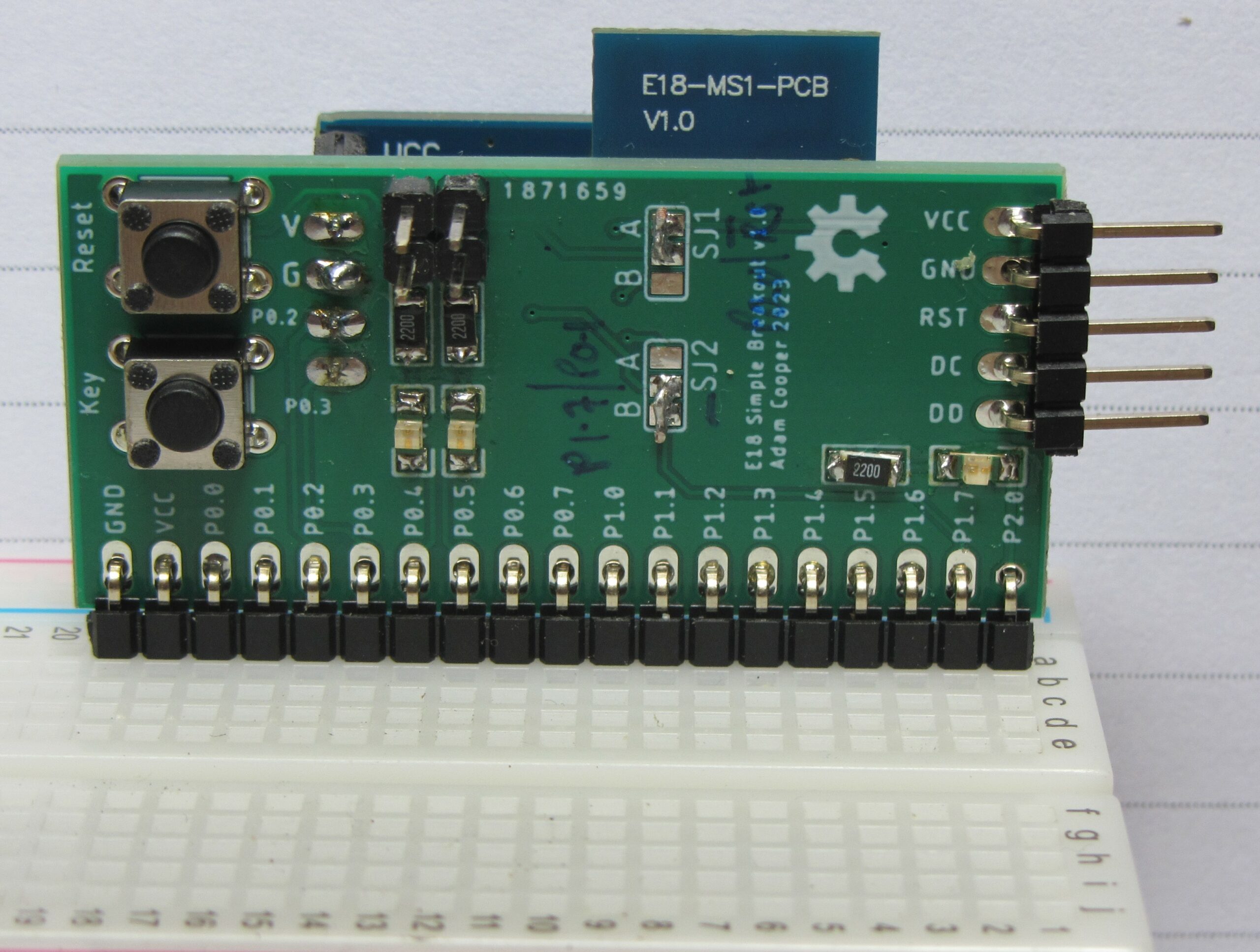
I would ideally like a genuine product, and while there are sellers proclaiming “genuine” in their listings, this often comes with an excessive price. Other than that, price seems to be a poor guide to quality. I consider a “clone” to be something which is functionally correct but not original and maybe with lower quality hardware. A module with the wrong firmware listed as “HM-10” is a fake, and if the core bluetooth chip (for these modules it is the Texas Instruments CC2541) is not correct it is a down-right fake. The last case is useless as it won’t be possible to load the HM-10 (or HM-11) firmware, which is available for download. Re-flashing is not particularly difficult, but generally involves some “hacky” soldering. Partially to alleviate the hassle of re-flashing but also to give me access to more of the CC2541’s pins (the HM-10 has lots of GPIO, ADCs, DS18B20, DHT11, and a poor-mans PWM), I designed some breakout boards and got a batch made. The Eagle CAD files are on GitHub, along with some links to software/instructions on reflashing.
It’s not that I wasn’t aware of the potential for fakery; I tried to assess listings by checking for ambiguous or garbled wording (almost universal!), clearly inaccurate descriptions, and checked the photos to see “CC2541” on the chip. I thought the most likely outcome was getting a module with an out-dated version of the hardware. I was wrong!
HM-10 Fail #1
On May 6th 2023, I bought two “HM-10” modules on breakouts from ebay seller Alimodule. The total price was £8.02, by no means the cheapest on sale. The breakout has a 5V regulator and [probably] some level shifting to allow it to be used on a 5V Arduino. I really wanted 3.3V supply and logic to work with an ESP8266, but I reckoned these would be OK to experiment with, and that I could butcher the breakout to achieve this. The downside of these boards is that they only expose the UART + status and key pins. The upside is that they are widely available.
After some stumbling about trying to follow the Huamao manual (and failing) it became clear that the firmware was wrong. THe device appears as “BT05” (which I later found out to imply some Bolutek firmware, although I never found documentation for it) and the result of AT+HELP shows the commands are wrong for HM-10.
I tried multiple times to flash new firmware, using both ESP8266 CCLoader and Raspberry Pi CC2541 programmer (see the GitHub link above) and got nowhere. The firmware appeared to upload correctly but the module appeared to be bricked. After SOME TIME, I realised that the chip id which is reported by the RPi programmer showed the chip was a CC2540, a TOTAL FAKE, even though the chip is clearly marked CC2541. Although these two chips are compatible at the source code level (I believe), they are not compatible at the level of compiled firmware. I tried REALLY HARD to find some firmware to run on the CC2540 but failed, so while the product which arrived would have worked as a simple serial-over-ble device, I now have junk!
I got a full refund, but no compensation for the lost time in working out I had a deliberate fake.
Avoid Alimodule!
HM-10 Fail #2
This time and for all the attempts below, I got “stamp” SMD modules to suit my shiney new breakout PCBs.
Ebay seller h-quality_electronic had a somewhat garbled description but a clear title – “HM-10 4.0 Bluetooth UART Transceiver Module Serial Port CC2541” – and a picture which looked OK; although it was missing one of the two SMD crystals (a common sign of a cost-reduced knock-off), the chip was right. I ordered 2 pieces for £6.80 delivered.
Unfortunately, it was the same story as before. The firmware claimed to be BT05 (and this was marked on the board) but many of the commands shown by executing AT+HELP simply returned “ERROR”. The chip id was read to disclose that this was another total fake with a CC2540 marked as CC2541. Seriously, someone went to the trouble of faking the markings on chips on a module only retailing for a few pounds!
This one ended with ebay customer support issuing me with a refund. Avoid this seller.
HM-10 Fail #3
Ebay seller cayin35 had a credible listing; it only mentioned CC2541, gave specific firmware versions, and the picture looked right. With only a few inconsistencies in the description I went for it: 2 items delivered for £6.82.
Sadly, the same story: crappy BT05 firmware with commands that don’t work and a chip which turned out to be a CC2540 when interrogated by a programmer. More TOTAL FAKERY.
A full refund again and another seller to avoid!
Now I am getting a bit pissed off. It really shouldn’t be this hard to get an item as it is described. This isn’t a matter of minor detail; these devices are NOT CC2541 and NOT HM-10.
HM-10 Success (partial)
Four boards from Aliexpress seller “Advanced Tech” cost me £12.91 including tax and postage. The description seemed mostly accurate for a HM-10, with the exception of chip ambiguity at the bottom of the description: “HM-10 CC2541 CC2540 4.0 Bluetooth UART Transceiver Module Transparent Serial Port”. I believe very early HM-10s did use the CC2540, which might explain how this comes about, but still. The picture did show a CC2541 and two SMD crystals (which is generally a sign of not cutting corners), so I gave it a shot.
These arrived today, August 10th 2023. It really has taken since May to cycle through order – wait – receive – test …
The hardware appears OK and the items received do look like the listing picture. The firmware advertises itself as HMSoft via a BLE scanner but once I started to interact with the device using AT commands it quickly became clear this is crap: AT+HELP? lists commands which dont all work (e.g. AT+VERSION returned nothing). AT+VERS? (which is the command used in a real HM-10) DID return a version string: “HMSoftV004”. Obviously nonsense. Firmware is a FAIL!
The Bluetooth chip is, however, a CC2541 (or at least it reports a chip id which matches, when queried by a programmer). And yes, miracle… I managed to flash it with a v540 firmware using the Raspberry Pi CC2541-programmer software. This isn’t the latest firmware but it is what I had in “.bin” form, and it supports updating over the serial interface using AT+SBLUP.
I’d have preferred not to have the hassle of a re-flash, but I’ll consider trying this seller in future as the evidence so far is that trying a new seller is more likely to waste my time and give me more junk than not.
HM-11 Fail
My first attempt to get some HM-11 was from ebay seller satisfyelectronics. Two items for £4.05 including tax and postage should maybe have alerted me to fakery but the title lacked the usual ambiguity about chip: “Bluetooth 4.0 module BLE CC2541 low power NEW HM-11 S“.
When the modules arrived it was immediately clear these were not HM-11 devices. The chip is not a Texas Instruments chip (CC254x)! By comparison with the Huamao datasheet and my HM-11 breakout boards it is obvious thath the module solder pads are all wrong. I should have spotted that in the photo. I can’t even test these and don’t know what they really are.
What egregious mis-description! I got a full refund.
Avoid satisfyelectronics!
HM-11 Success!
Aliexpress seller “fYD Open Source Hardware“. I bought 4 for £12.98 including tax and postage. The listing did give me some cause for concern as the title included “CC2540” (wrong!) and “CC2541”. The picture did show a CC2541 and two SMD crystals (which is generally a sign of not cutting corners), so I gave it a shot.
These were either genuine or good fakes. Hooray! The firmware was not the latest, being v6xx, but that is new enough to allow for firmware updating via the serial port using “AT+SBLUP” and the Huamao upload tool. The listing actually stated firmware v508.
I suppose there is no guarantee that they still have the same batch, and some of their other listings had garbled descriptions, but I would try them again.
Final Words
It is pretty clear that pictures and descriptions are not a good guide. If you find yourself in the same situation, make sure you check the chip id. If it is wrong demand a refund and avoid that seller.