Making a Trepanning Tool – Notes and Plans

I’m planning on cutting some gear wheels and, having struggled with using a hole-saw to cut blanks, decided a trepanning tool was probably the answer.

The tool is only meant for cutting 1/8″ thick stock. Tested on brass and aluminium (may not be up to the job with steel). Use low speeds and if you don’t know what you are doing, don’t do it!

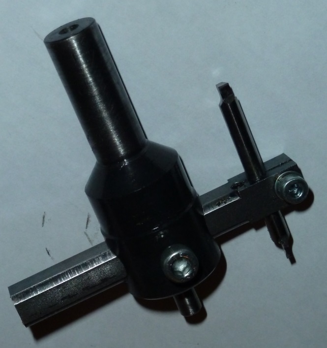
The Finished Trepanning Tool

The dark colour of the main body is due to a (failed) attempt to case harden the pilot; it is just uncleaned scale from from heating. I actually found the setup to be sufficiently rigid that the pilot didn’t take any load with 1/8″ brass and the narrow cutting tool shown below in the bottom right of the picture.


Trepanning Tool (click for larger size)

The Plans

These are not proper dimensioned drawings in an engineering sense, and were produced as part of the design process, but they should be sufficient. Stock used was steel 1″ dia bar and 3/8″ square.

Trepanning Tool Assembly (click to open full-size image)

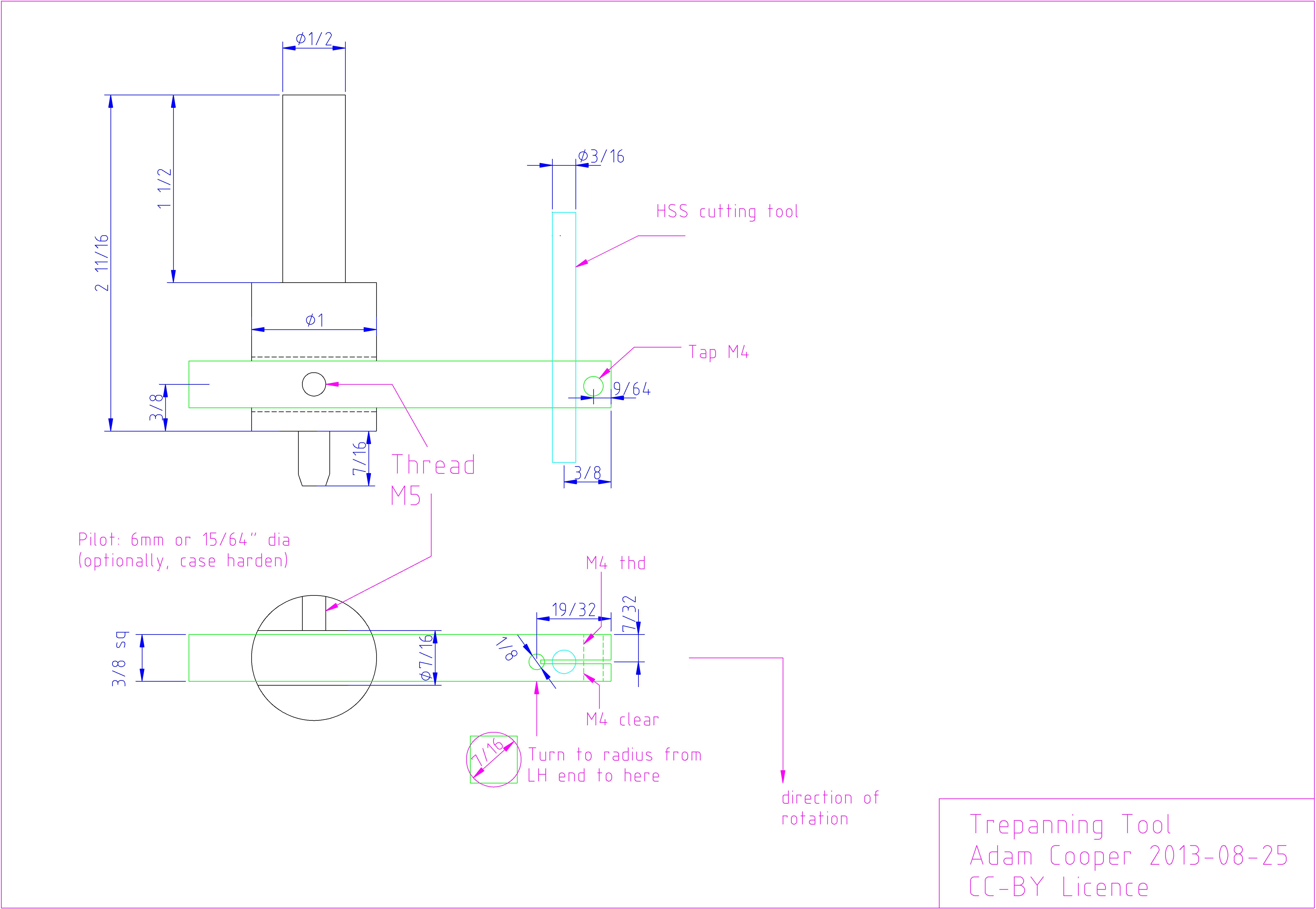
Also available as a DXF File.

Brief Construction Notes

Arbor

Cut 1″ dia stock to slightly over length

3 jaw chuck :-

  • face off (light cuts), centre drill and support with tailstock centre
  • turn down 1/2″ shank
  • brighten up about 1/4″ of 1″ dia body (used later for concentricity setting with DTI)
  • cross-drill, widening progressively to 7/16″ (ideally finish to size with reamer)
  • drill and tap M5 (and shorten M5 cap screw to match)

4-jaw chuck :-

  • hold using 1/2″ shank, adjust to near zero runout with DTI
  • turn pilot (should be concentric with shank)

Cutter Arm

3/8″ square stock

4-jaw chuck :-

  • face off both ends (low overhang from chuck)
  • centre-drill second end, loosen 2 adjacent jaws, withdraw from chuck and support on centre, retightening the jaws to same setting
  • turn to 7/16″ dia to fit arbor

Pillar drill :-

  • drill and ream 3/16″ for cutting tool
  • drill 1/8″ for end of slot
  • drill for clamp bolt (M4 tapping drill size)
  • cut 1/32″ slot
  • drill clear for clamp bolt (up to slot)
  • thread M4 for clamp bolt

The Cutting Tool

Grind a 3/32″ or 1/16″ wide cutting point. Give it plenty of side clearance because the tool will be making an arc. Tighter arcs => more side clearance will be needed at the expense of a weaker tool.

Since round tool steel is used, the cutter can be rotated to adjust the in-use clearance a little to compensate for slightly uneven grinding, and changes in cutting radius, but I suppose the cutting face should be fairly close to lying on a radial line.

Making Elmer’s “Tall Vertical Open Column”

The late Elmer Verburg designed quite a few relatively-easy-to-build model engines. All are made from bar stock. The second one I have made is #32, the “Tall Vertical Open Column”. As many people do, I made a number of minor changes. These are described here, along with some construction notes I wrote to help myself, some observations and some pictures.

The plans can be found online in several places: there are several “Yahoo Groups” as well as “jon-tom.com“. I have also uploaded them (see “Files” section).

Notes and Comments

I opted not to paint the base and top platform, having previously made a mess of painting. Instead, I left them relatively “raw”: the as-rolled large faces of the bar stock were very lightly cleaned up and the edges were draw-filed. I’m fairly happy with this approach and like the contrast with the shiny flywheel and brass components.

In the interest of simplifying construction – and reducing the need for careful working, which is not my strong point – an alternative method of constructing the eccentric sheave and the arms that ensure a straight-line motion of the piston rod were used. See the “Files” section below.

The only problem encountered on assembly was that the straight-line that the arms followed did not match the piston rod. It is worth making the holes on the base plate of the cylinder assembly a bit slack to allow for adjustment but I ended up having to insert a 15 thou shim under one corner to get the motion to be “good and free”. I suspect that this is due to having used quite small AF hexagon rod for the columns such that it didn’t pull itself square on tightening. On the other hand, it could simply be a misplaced hole.

Quite a few of the joints leak slightly – see the video – since I just left them as metal-on-metal.

Some other examples on the web:

Files


Making Dice in Brass (or other metal)

Here are some notes on making dice (or just one die) in brass (etc) in the metalwork shop, suitable for a total beginner. I did it with my 10-year old. I used some half-inch square brass stock.

  1. Set the stock in the lathe using a 4 jaw chuck. Get it close to centred by sighting the edges against the cutting tool. I tend to face off with a TCMT (carbide tipped) tool where the tip points away from the tool post (i.e. a 60 degree angle to the work). I used my top speed of 1800RPM but you could go faster.
  2. Face it off.
  3. Mark out and cut off slightly over 1/2″ from the stock, file it down a bit to remove the unevenness.
  4. Fly-cut (1″ or slightly larger fly cutter) the sawn face to get to a cube.  Use a speed of about 1100 RPM and work in stages of measure-then-cut. This is quite easy even in a small mill/drill. Lock the table in position and the head in place while cutting. A digital scale on the vertical axis is really useful for this (the vertical fine-feed on my machine is hopeless) . An alternative is just to face-off this end in the lathe but I find it easier to finish off at the correct length flycutting and it demonstrated the technique.
  5. Gently remove rough or sharp edges with a fine file or emery paper.
  6. Set up an arrangement like the photo. The tool clamp provides a positive location so that the die can be turned over and around and returned to the same position.
  7. Turn the cube over so that the previously-turned face is upper-most. Fit a centre-drill into the chuck with a point of the size you want the die dots to be. Traverse the milling table so that the centre of the face is lined up. The marks from the facing-off operation should be sufficient and give a nice appearance. (this is why you need to get it “close to centred” in step 1). Make sure  you remember to take account of backlash in the leadscrews. I made sure I approached the centre by turning the handwheels in a clockwise direction. Zero the collars or mark off the handwheel positions carefully.
  8. Drill to depth. Set the depth-stop and drill again to meet the stop.
  9. Remove the die, rotate to another face, snug-it up against the tool clamp and secure the die. Drill another centre hole (say for the “3” side) then a final hole (say for the “5” side). Remember opposite sides of dice add up to seven.
  10. Decide where the corner dots will be and traverse both axes of the milling table to position the cube appropriately. Traverse the same distance for each axis. I opted for a whole number of revolutions of the handwheels for simplicity. Remember to turn them the same way as in step 7 to mitigate for backlash.
  11. Reclamp the table and drill a dot. Loosen the milling vice and rotate the die by quarter of a turn. Repeat until you’ve made the “5”. Use the same process to make the “3”.
  12. It should now be obvious how to make the “2” and “4”. The “6” is made by making a “4” then return one of the milling tables to its “zero” position (step 7). Reverse back past “zero” by about half a turn of the handwheel them advance back to “zero”. Clamp the table and drill. Rotate half a turn and complete the last hole.
  13. Polish it up, slightly round off the edges and corners and you are done.

My daughter was well pleased with the result and rather impressed by the simple little tricks that make it quite easy to get a neat and regular result with minimal fuss and fiddle: the trick with the tool clamp, rotating the die, the depth stop. If I were to make another, I think I would place the “spots” slightly further from the edges.

Wallace & Gromit Inspired Arms in Brass/Steel

Here is the product of a fancy, something less demanding than making something that really works. It was made relatively quickly from a page of sketches I made over a cup of coffee so it isn’t perfect. I’d probably change some details if I made another.

I’ve written some construction notes and transcribed my pencil sketches to a CAD drawing in case anyone finds that useful. I’d be pleased to hear of any improvements anyone makes.

Download: Zip of plans, construction notes and larger pictures (770kB total).The CAD plans were made using Draft-IT (by CADLogic) but a lower res GIF is included in the zip)

Cheers!

Model Watt Governor – CAD Plans and Construction Notes

Having had a hankering to make a Watt-style governor but having failed to find any plans to my taste, I decided to design my own. Here it is, with 2D CAD plans produced with Draft-IT (and GIF images of the same) and my construction notes for download. The design is hand-cranked and lacking a valve lever because it was made as a retirement/60th birthday gift and I ran out of time to complete the valve lever (I wanted to assemble the governor before dimensioning the lever).

Inspiration for the design, and especially the proportions, came from Muncaster’s book and photographs I took of real governors.

All of the downloads are covered by the same Creative Commons licence as everything else on this blog. Feel free to adapt but I’d like to hear about modifications, ideas etc…

Downloads:

Paradoxical Cones – the Uphill Roller

I came across an account of the “uphill roller” in a book by Julian Havil, “Nonplussed!”. The basic idea is that two cones, joined at the bases, will appear to roll uphill on a pair of diverging rails if the combination of the angles of the cones, slope of two rails and divergence of two rails is within certain margins. Julian’s article explains the mathematical analysis and gave a simple inequality.

That looks cool, I thought, and the challenge of machining two con-joined cones appealed too.

I decided to design an adjustable set-up that would demonstrate conditions when the cones would appear to behave paradoxically and conditions when the would not. Somewhat to my surprise the finished article worked as inteded.

Downloads:

  • CAD Drawings – Draft-it format
  • CAD Drawings – GIF Images
  • Machining notes

I’ll upload a video when I have one…