Having recently wanted to get my hands dirty with DIY Zigbee – see my other post on low cost DIY Zigbee – I couldn’t find any suitable breakout boards so, after having found the CC2530-based Ebyte E18-MS1 modules (which are rather economical and available from the manufacturer on Aliexpress… and seemingly without the curse of a glut of clones and fakes), I decided to make my own.
I wanted something quite simple but also flexible, with maximal scope for experimenting and learning. The main use case is to plug into breadboard but there was enough PCB space for some “convenience” components: two switches and three LEDs and associated resistors.
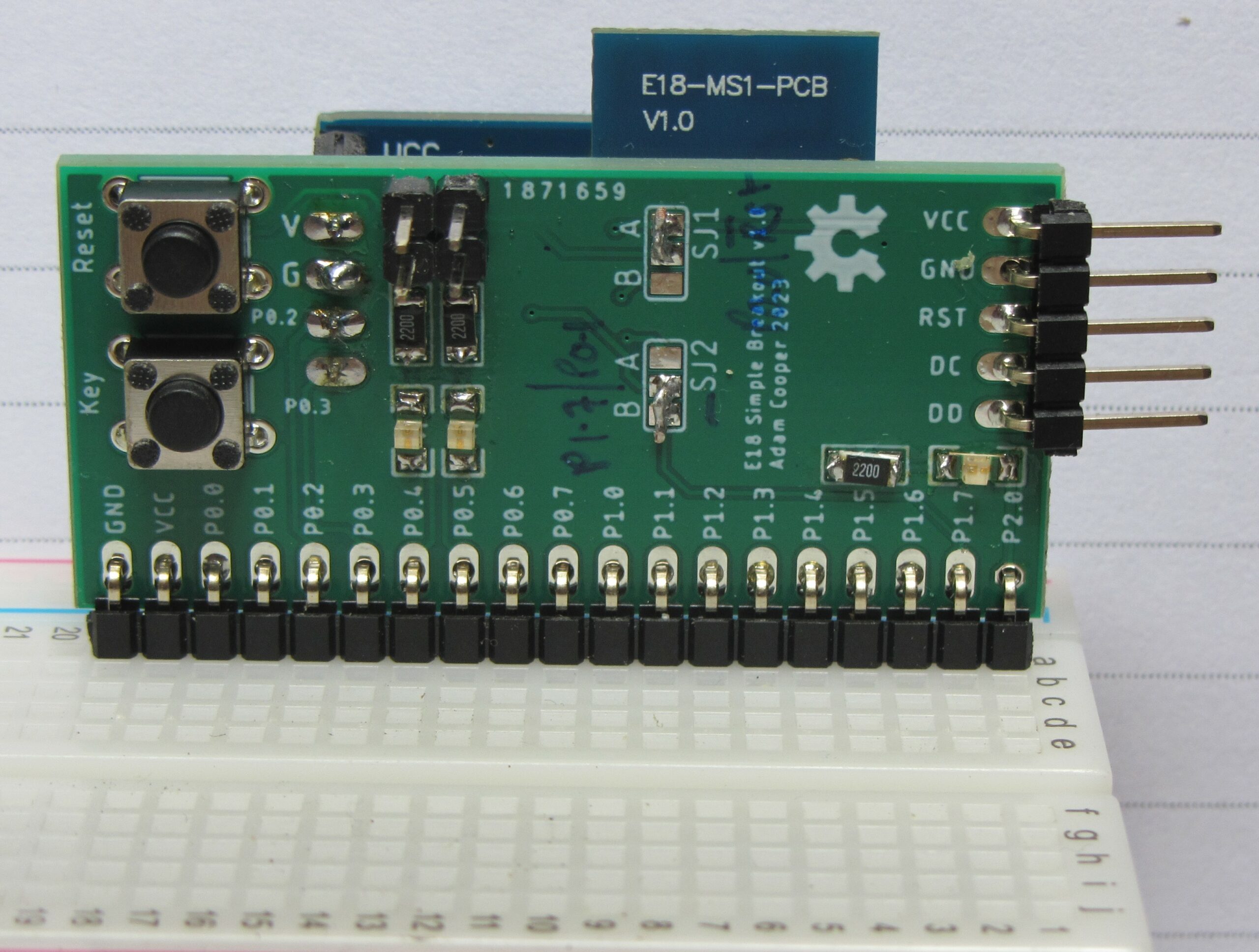
This is what it looked like once assembled (you can just see a BH1750 I2C light sensor on the rear):
Some notes on motivation, layout pragmatics, and options:
- The long header is meant to be populated with right-angle pins. This will put the antenna nicely up and leaves plenty of space for other components on the breadboard (I find the breakouts with very wide dual-in-line pin-outs to be rather irritating, and Arduino style sockets and flying leads are not great when more than a few connections are to be made).
- The 5 pin header is for firmware flashing. I opted for this, rather than the full 10 pin “debug” header which CCDebugger uses, for econonmy of space. These 5 pins are quite sufficient for using CCDebugger with TI SmartRF Flash Programmer (I made a little adapter) or if using something like Flash CC2531, which works fine for CC2530’s, (or my patched version for use with Pi v1 GPIOs).
- The 4 pin header may be convenient for either UART or I2C connections. I’m expecting to be using PTVO and for the CC2530 it fixes UART pins to be P0.2 and P0.3. This header is meant to be mounted on the same side as the E18 module (opposite to switches).
- The switches should be configured using the solder jumpers.
- SJ1 handles the “Reset” button: A connects to E18 Reset; B connects to P0.0.
- SJ2 handles the “Key” button: A connects to P0.1; B connects to P1.7 (which is used by the E18 factory firmware).
- The on-board LEDs (and the enabling jumpers) visually correlate with the pins they are connected to: P0.4, P0.5, and P2.0.
Eagle design files are available on github but I am also currently (July 2023) selling surplus PCBs on ebay.