This post is motivated by the lack of information about using debugWire with an Arduino (or similar) on the web. There are quite a few brief comments on the forums and people asking how to do it but nothing really good, with the possible exception of a post by Steve Cogswell which refers to an old version of Arduino and an old version of Atmel Studio.
This really notes for myself for next time, when I’m bound to have forgotten the recipe, but I hope someone else will find it useful. The previous post describes how to get started with using the Atmel Studio simulator, which is a good introduction to the activities required during on-chip debugging (OCD) without needing to fiddle quite so much and without wondering whether the hardware is playing nicely.
What Can You Do with debugWire?
Inspect memory, single-step through code, set break-points (at which execution will stop), inspect registers and input/output port values etc. i.e. as for the simulator, but for the real hardware.
Pre-requisites
This assumes you have:
- an Arduino Uno
- Atmel Studio 6 (Windows only but you could try using it from inside VirtualBox if you are a linux or Mac user – I’ve had a good experience of VirtualBox on Ubuntu, although I’ve not tried Atmel Studio )
- an AVR Dragon (a fairly cheap USB programmer/on-chip-debugger) and a 6-way cable to connect it.
I also recommend you get the ATMega328 data sheet.
Preparing the Hardware
The ATMega328 data sheet says:
• Capacitors connected to the RESET pin must be disconnected when using debugWire.
• All external reset sources must be disconnected.
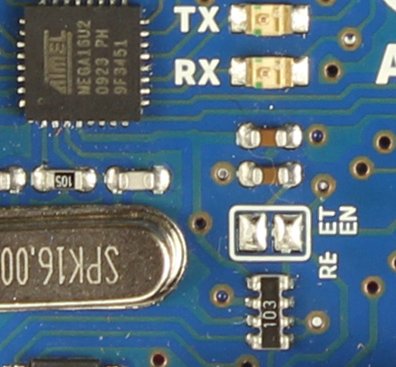
If you check the Arduino Schematic, you will see that there IS a 100nF capacitor connected to RESET. This is used to cause a reset to be triggered when communication is initiated via the USB. This is normally useful since a reset is needed to prompt the bootloader on the Arduino to receive compiled code in the upload process.
In the older Arduinos you had to remove the capacitor (as per Steve Cogswell’s post) but on the Uno there is a bit of circuit board track specially prepared for cutting and re-soldering later if need be. If you leave it cut then it will be necessary to manually press the reset button just as the Arduino IDE (or avrdude) tries to start an upload.
Preparing the Software
This is basically just a case of compiling the code for the Arduino in Atmel Studio as I’ve previously described. It is NOT necessary to upload the compiled code using avrdude because Atmel Studio will do this for us via debugWire.
Preparing the Hardware
Connect the Dragon ISP header to the Arduino ISP header. Note that pin1 connects to pin1 on the other device, i.e. MISO connects to MISO. Both Dragon and Ardiuno are separately powered through their USB connectors and the Dragon senses the Arduino’s power supply voltage through the 6-way connector.
Open the device programmer using Tools|Device Programming menu or: ![]() .
.
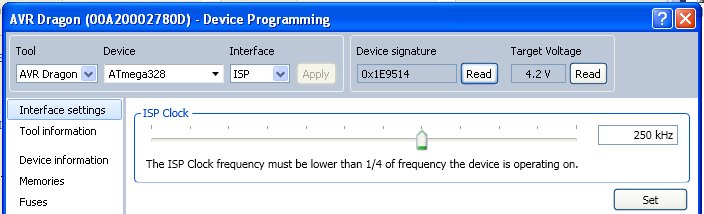
You can also “Read” the device signature to confirm that the physical device matches the one chosen in Atmel Studio. This will happen automatically later on anyway and Atmel Studio will block you if it isn’t right.
Warning… and Being Prepared
As described in Steve Cogswell’s post, it is possible to make a non-permanent mess of the ATMega328. It may be necessary to use the “HV” programming on the AVR Dragon if the ATMega gets stuck in debugWire mode and it may be necessary to re-install the boot-loader. These are not difficult if you have an AVR Dragon (or presumably other programmers too).
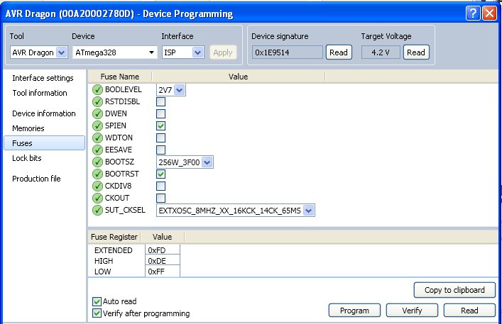
It can be useful if you need to recover from mishap, and is generally a good plan, I think, to get the fuse settings BEFORE messing about with debugWire and before fiddling with them. All you need to convert a factory fresh ATMega328 into something usable on an Arduino board is to set the fuses correctly and to program the boot loader.
The debugWire Cycle
This is the sequence of operations I have found works reliably. Try this with “Blink” (if you’ve carried on from the simulation example, remember to replace the delay() lines). NB: step 7 is important to get your chip back into its normal state.
- Program the DWEN fuse: make sure the box is ticked then click “Program”.
- Cycle the power on the Arduino by temporarily disconnecting the USB connector. At this point, you can probably no longer use the ISP interface.
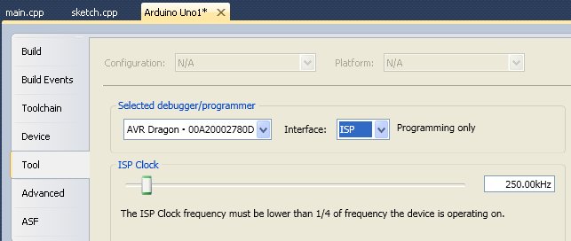
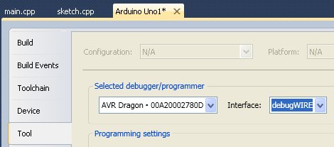
- Set debugWire as the interface (see screenshot below)
- Click “Start Debugging and Break” or hit Alt+F5 or set a break-point then “Start Debugging” (F5). Note: this uploads the program too.
- Set break-points, single-step etc. Use the “IO View” to manually change the value of output pins on the Arduino, yes, the real ones!
- Stop debugging (Ctrl+Shift+F5), change the code and return to step 4.
- Menu “Debug|Disable debugWIRE and close”. This menu item is only accessible when debugging so you may need to use F5 again. The DWEN flag will now be reset and you will be able to use the ISP interface again.
Now compare the fuses and lock-bits to the previously saved settings. They should be identical. debugWIRE should also have preserved the bootloader so it should be possible to go back to the Arduino IDE; you only need to remember to press the Arduino reset button just as the IDE announces it is uploading in order that the bootloader executes.
hi
i have a question: at point 4 of your tutorial on which way will be the upload done? The USB reset is cutted so there cant be an upload done and also the ISP is disconnected thru the DWEN enabling?
it would be very nice if you can answer this
thx
hape
Two points here:
1. if the USB reset link is cut there are two options:
– solder it back together (I now have a jumper soldered in place so I can easily enable/disable the auto reset).
– manually press the arduino reset button just as the upload starts (it may take a few attempts to get the timing right).
The point is to put the ATMega328 into its reset condition, which (unless you change the default fuse settings) cause the bootloader to execute. The USB auto-reset just uses a serial port communication signal to trigger the ATMega into reset using exactly the same pin as the manual reset.
2. If the DWEN is stuck (a known “gotcha”, and the price of experimenting) then you will probably have to use a programmer like the AVR Dragon for “HV” programming or just buy a new ATMega328. There are people who sell them on ebay with the “optiboot” bootloader already installed and the correct arduino fuse settings. Just buying a clean device from farnell/digikey/etc will not be ready to use.
Cheers, Adam
In case I will use Arduino board without USB connector I assume direct connection of ISP and DW is possible (without capacitor surgery). Like with Pro Mini board (ATMega328P) and Atmel JTAG ICE 3.
Programing and debuging could be possible in Atmel Studio 6.2.
Plese tell me if Im wrong.
Thank you.
Thanks I had just bought an Atmel_ICE and it wouldn’t go into debug until I found this post. Thanks man!
Thanks Mike.
Like your site, by the way.
You may find this ATMEL video helpful: https://www.youtube.com/watch?v=Bo0spmIKCy4
Hi Adam,
Thanks for this tutorial. I have been slurping it up as much as I can. I am new to AVRs and especially AVR Dragon. I wanted to setup my arduino to be able todebug on-chip programs.
I bought a AVR Dragon and did program the DWEN fuse and now its stuck in debugWire Mode I cannot get it out by recycling as you indicated. The board did not have a solder pad so I went ahead and removed C5 (100nf) from the surface mount. I decided it was the C5 that needed to be removed based on the schematic I found on internet for Arduino UNO R3(the one I have). Here is the schematic I looked at : https://www.arduino.cc/en/uploads/Main/Arduino_Uno_Rev3-schematic.pdf
Can you please let me know if you can think of probable causes. I know I have the DWEN enabled as I cannot access the board in ISP mode anymore. However, when I start to debug, it says that either the reset circuit is wrong or the DWEN fuse is not set. It aborts after that as with an error messages stating that it got 0x0c when it expected 0x00. Any help or indicators will be much appreciated.
I bought this one from ebay. http://www.ebay.com/itm/381264364294. Hope you can look into my message. I feel pretty bricked 🙁 !
I agree C5 was the correct decision.
You could try to remove the resistor and diode attached to pin1 of the AtMega328.
You are not the first to get a brick! They are cheap enough at least…
At the price you paid, I’d be concerned this may be a clone device, which might explain things.
Further options:
– be adventurous and get an SMD rework station, buy a new ATMega and replace it. totally bonkers, cost-wise, but if it works…
– buy a new board with a DIP ATMega then you can replace it easily
Its a learning experience!
Cheers, Adam
Hello Adam. I wanted to thank you so much for this tutorial, it was exactly what I was looking for and indeed there are not a lot of tutorials for this purpose out there. I would have never though that I needed to carve(that’s what I did) that small path for the reset.
Especially thanks for clarifying that the uploading can be done through dWire. Somewhere in the documentation from Atmel on the Dragon, they explain it in such a way that I though you needed to jump from ISP to dWire to do the programming and debugging.
All the best!
Thanks Adam for this article. The screens look a bit different in Studio 7 but it’s still very helpful.